Verification and validation (V&V) are foundational engineering disciplines required to guarantee that a safety-critical system fulfills its specified safety requirements and operates reliably under all defined operational profiles. Within functional safety standards such as IEC 61508 and ISO 26262, V&V acts as the technical mechanism that mitigates systematic faults.
To use a common engineering analogy: verification evaluates whether the system was built correctly according to the design specifications, whereas validation evaluates whether the correct system was built to satisfy the end-user's actual operational needs.
Importance of V&V in Safety-Critical Systems
Implementing a structured V&V framework is a non-negotiable prerequisite for passing third-party functional safety audits and achieving regulatory compliance.
Enforcing Regulatory Compliance:
Compliance with master standards like ISO 26262 (automotive) and IEC 61508 (industrial automation) requires strict bidirectional traceability between initial safety requirements, design implementations, and completed test records. V&V processes ensure that every safety requirement is fully executed, verified, and legally documented.
Systematic Error Elimination:
Unlike random hardware failures, systematic errors are introduced through flawed specifications, software bugs, or incorrect architectural assumptions. Rigorous V&V catches these design errors early in the V-model development lifecycle, significantly improving the overall quality and reliability of the platform.
System Risk Mitigation:
Unmanaged defects in a safety loop can lead to dangerous undetected failures. Identifying, isolating, and resolving potential functional anomalies before field deployment directly minimizes the probability of catastrophic safety incidents.
Stakeholder Credibility:
Providing documented, objective evidence of rigorous V&V testing builds absolute trust with corporate procurement teams, regulatory authorities, and end-users, protecting the organization from severe operational liability.
Hierarchical Architecture of Verification
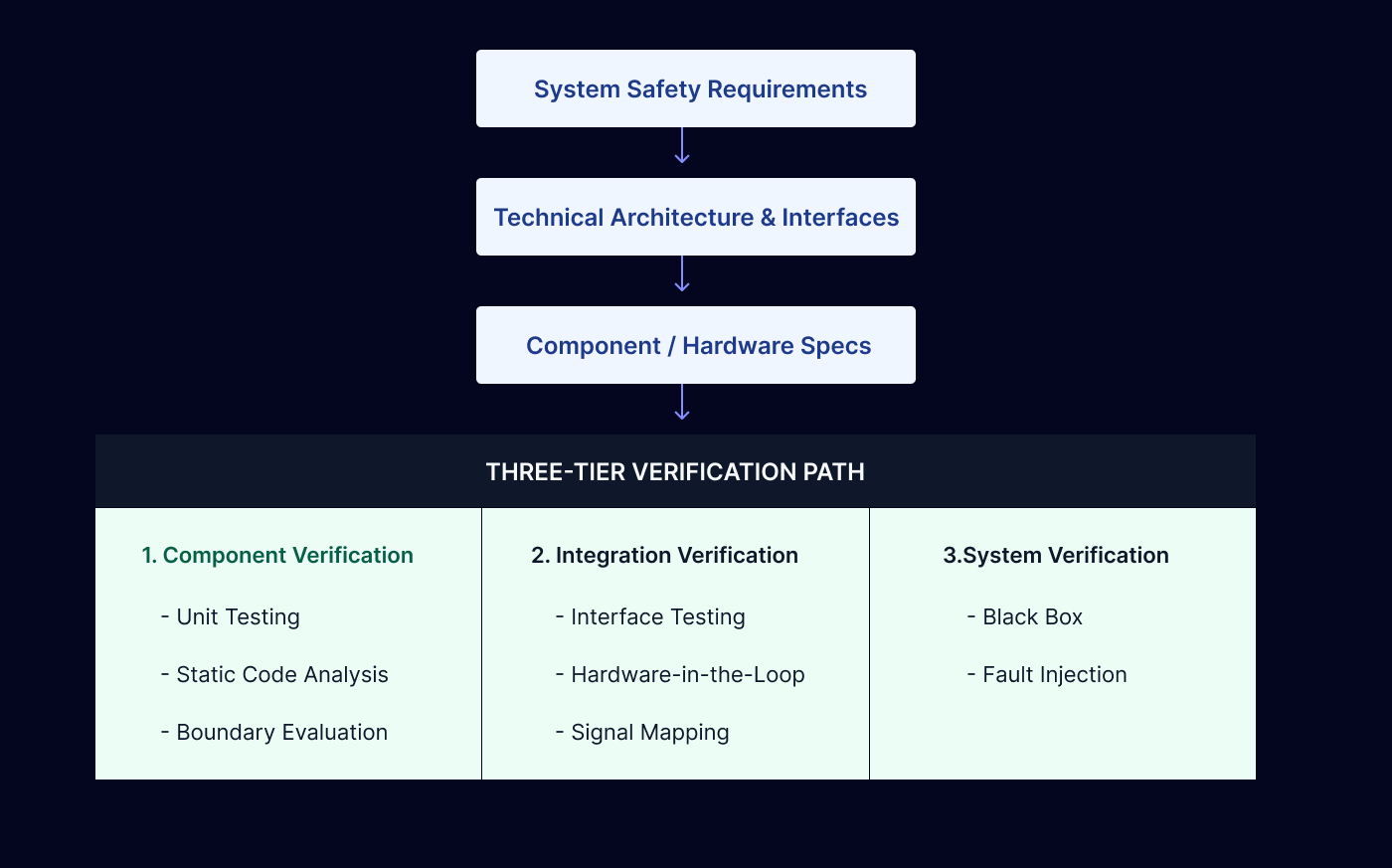
Verification is an iterative engineering activity executed at every stage of the development lifecycle. Under IEC 61508-1 Clause 7.14 and ISO 26262-4 Clause 9, verification must be conducted across distinct, progressive levels of the system architecture to confirm that the phase outputs match the phase inputs.
1. Component Level Verification (Clause 5.5 / Part 6)
This initial stage focuses exclusively on evaluating individual hardware components, modules, or software units in complete isolation. The goal is to verify that the element functions exactly as specified by its low-level requirement sheet.
Execution Methods:
Static code analysis, software unit testing, code coverage evaluation (e.g., Statement, Branch, and MC/DC coverage), boundary value testing, and hardware component stress testing under thermal or electrical extremes.
2. Integration Level Verification (Clause 5.6 / Part 5)
Once individual components are verified, they are progressively combined into functional subsystems. Integration verification focuses on the interactions, data exchanges, and electrical interfaces between those components to ensure they cooperate seamlessly.
Execution Methods:
Hardware-in-the-Loop (HIL) simulation, network protocol verification (e.g., verifying PROFIsafe or CIP Safety frame timings), timing analysis, signal integrity checkouts, and software module integration testing.
3. System Level Verification (Clause 5.7 / Part 4)
System verification evaluates the fully assembled system as a unified entity. The objective is to provide objective evidence that the integrated hardware, software, and physical interfaces satisfy every high-level safety requirement under all expected operating states and environmental conditions.
Execution Methods:
Black-box functional safety testing, fault-injection testing (deliberately introducing short-circuits, broken wires, or corrupted data to verify the safe-state transition logic), and electromagnetic compatibility (EMC) testing.
Validation: The Real-World Proof Case
Governed by IEC 61508-1 Clause 7.15 and ISO 26262-4 Clause 10, safety validation stands as the final evaluation phase before a system is certified for live operational deployment. While verification is focused on design compliance, validation tests the entire system within its actual, unstimulated operational environment against real-world scenarios.
The primary objective is to prove that the protective mechanisms engineered into the equipment effectively eliminate hazards and reduce risk profiles to acceptable targets under the control of the actual end-users.

Validation requires testing the equipment under worst-case stress profiles, documenting human-machine interface (HMI) responses, and confirming that the system handles complex, unpredictable environmental variables without presenting an unreasonable risk to operators or surrounding assets.
Enterprise Tooling and Engineering Infrastructure
Managing V&V for complex, high-integrity systems becomes unmanageable using standard spreadsheets or decoupled text files. Complex functional safety programs require specialized enterprise engineering tools to automate workflows, maintain audit readiness, and prevent compliance gaps.
Application Lifecycle & Requirements Management (ALM/RM)
Tools like IBM Rational DOORS, Jama Connect, or Siemens Polarion act as the centralized compliance ledger. These platforms host the safety requirements specification, automatically generate bidirectional traceability matrices, and map individual requirements directly to physical implementation items and specific validation test cases. This end-to-end mapping prevents "orphaned features" and guarantees to external auditors that every safety goal has been validated.
Model-Based Design and Simulation Environments
Engineers leverage tools like MATLAB/Simulink to build exact mathematical representations of safety functions, control loops, and physical system dynamics early in the concept phase. By running automated simulations, teams can validate safety algorithms, execute virtual fault injection, and catch systematic architectural errors before manufacturing physical prototype hardware, significantly cutting down on engineering cycle times.
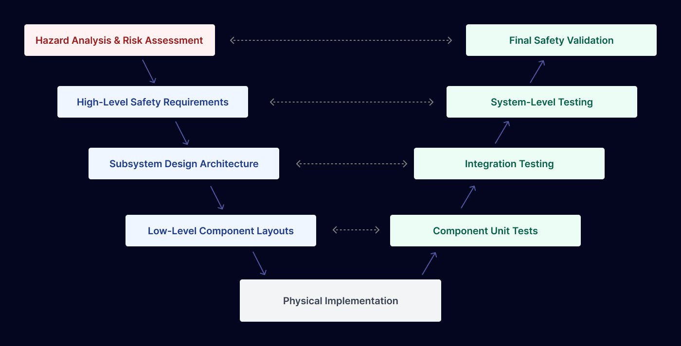
System Development and Validation Lifecycle Diagram
The graphic below illustrates the bidirectional mapping required across the system development lifecycle. Every phase of development on the left column must be explicitly verified and validated by its corresponding testing phase on the right column to build a defensible safety case.